The following is taken in full from Section IX. Optics, Heat, and Electronics; Chapter 3. An Inexpensive X-ray Machine The Scientific American Book of Projects for The Amateur Scientist Library of Congress Card Catalog Number: 60-14286
© Copyright 1960 by C. L. Stong
An Inexpensive X-ray Machine
From an old radio tube, some copper wire, and other inexpensive materials total cost: roughly $20 you can construct an X-ray machine that will make good pictures through an inch of wood. SAFETY MEASURES THAT YOU MUST OBSERVE. Notes on Röntgen's invention. Highlights of X-ray theory.
Harry Simons of 118 Windsor Street, Kearny, N.J., is a lonely amateur scientist. For 23 years, he writes, I have been dabbling in the X-ray portion of the electromagnetic spectrum without once coming across a fellow amateur. Thousands of enthusiasts can be found in the region of radio waves, of light and of gamma rays. But none of them come to play in my back yard. If the prospect of exploring fresh electromagnetic territory sounds interesting to any of these amateurs, I can promise good hunting in the 10-8-centimeter region and for a total investment of less than $20.
As a lure Simons offers the collection of radiographs reproduced in Figures 225, 226, 227 and 228. He takes special pride in the one which shows screws embedded in an inch-thick block of wood. This shot resulted from his first experiment with X-rays and illustrates what can happen when a fellow with a sharp eye follows a happy hunch.
figure 225 225 Simon's radiograph of two screws imbedded in an inch-thick block of wood
figure 226 226 Radiograph of the plug from an electric flatiron
figure 227 227 bones of fish revealed by homemade X-ray machine
figure 228 228 Effectiveness of Simon's X-ray machine in penetrating the steel leaves of a thickness ranging from .002 to .010 of an inch thick
During a rainy weekend back in 1933 Simons was fiddling with an Oudin coil. This almost forgotten gadget, a close relative of the Tesla coil, can step up low voltages 1,000 times or more. High voltage generated in this way has an advantage for the amateur experimenter in that it is relatively harmless. In the course of stepping up the voltage the Oudin coil also increases the frequency of the current, so that it tends to flow through the skin and away from vital organs such as the heart.
My original Oudin coil, Simons recalls, was part of an ultraviolet lamp with which I tested mineral specimens for fluorescence. For no particular reason I decided to replace the evacuated quartz bulb, which produced the ultraviolet rays, with an old radio tube of the 01 type. The glass envelope of these tubes is coated inside with a silvery film of evaporated magnesium the so-called getter which helps clear the tube of stray gas during the evacuation process and absorbs any that may be liberated by the glass walls or metal parts after the seal-off. I simply held the 01 in my hand and touched its prongs to the high-voltage terminal of the coil. Instead of filling with a lavender glow, like the quartz bulb, the inside of the tube remained dark but the glass in contact with the magnesium lighted with a pale greenish fluorescence that reminded me of the glow emitted by old style X-ray tubes of the gas type. Was the radio tube producing X-rays?
To obtain the answer to this question I put a narrow band of tinfoil around the top of the tube and grounded it as a substitute for the electrode previously represented by my hand. I then fished a small block of wood, which happened to have two screws in it, from the trash box and placed it on a sheet of photographic film wrapped in black paper. The combination was exposed to the energized tube for 15 seconds at a distance of seven inches. When I had developed the film, I discovered a wonderful radiograph of the screws plus a lifetime hobby that should appeal to anyone interested in physics.
Why has Simons's hobby failed to catch on? One reason is that commercial X-ray equipment is costly. Even tubes of relatively low power are priced at $100 and up. Many other commercial X-ray parts are also expensive and difficult to procure. The apparatus supplying high voltage to conventional tubes, while no more complex than the power supply of a husky radio transmitter, calls for special rectifying devices, transformers and other components which are not regularly stocked by dealers in electrical supplies.
Moreover, X-rays have earned a bad reputation as playthings. No distinction can be drawn between the danger of exposure to a high-powered X-ray machine and the fallout of an H-bomb. It is a danger that extends not only to the experimenter but to his potential progeny. Human evolution is the result of mutations caused by, among other agents, cosmic rays and the radiations of radioactive elements in the earth's crust. Any radiation added by man alters the rate of mutation, and is rightly a cause of deep concern.
Simons has solved the problem of equipment cost. Protection against exposure to the rays is not difficult to arrange. With these two considerations out of the way, X-rays open a range of experiments equaled by few other phenomena of physics. In addition to providing a source of X-rays for radiographs, a generator of X-rays in combination with accessories enables you to measure the charge of the electron, to study the structure of crystals, to observe the wave-particle duality of matter and radiation, and to probe other microcosmic corners.
Like visible light, X-rays are a form of radiant energy. Their ability to penetrate substances opaque to visible light, however, is neither unique nor particularly unusual. Many substances opaque to light are transparent to other electromagnetic waves. For example, long electrical waves, as well as the shorter ones of radio, pass freely through dry wood, plaster and other substances that do not conduct electricity and are opaque to light. If this were not so, all radio and television receivers would need outdoor antennas.
On the other hand, a thick sheet of flint glass, which transmits radio waves and light with no appreciable loss, stops X-rays. The ability of X-rays to penetrate substances like flesh and bone is merely their most publicized property. However, this property provides a striking case of the immediate application of a scientific discovery. Within weeks of the description of X-rays by Wilhelm Konrad Röntgen in 1895, surgeons heralded them as a tool of the first importance.
They are characterized chiefly by extremely short wavelength about one ten-thousandth the length of visible light waves. Like light waves, X-rays can be reflected, refracted, diffracted and polarized. The techniques by which they are manipulated differ from those employed with light, just as light techniques differ from those of radio. The longest X-rays are indistinguishable from ultraviolet rays; the shortest are identical with gamma rays. The distinction between the two is largely a matter of definition. When the emission accompanies the disintegration of a radioactive substance such as radium, it is called gamma radiation. Identical waves generated by electronic means are called X-rays.
All radiant energy, including X-rays, has its origin in a disturbance of electrical charge. Consider a point charge an electron surrounded by a symmetrical electromagnetic field and moving through space at constant velocity. What happens to the motion of the field if the central charge is speeded up or slowed down? Experiments indicate that the field reacts much like a mass of jelly. When the central charge is accelerated, the disturbance is communicated radially through the field as a wave motion the outside parts of the field requiring an appreciable time interval to catch up with the center. Work expended in accelerating the central charge is carried away by the wave as radiant energy, at a velocity which depends on the nature of the jelly.
In a vacuum the wave attains a maximum velocity of slightly more than 186,000 miles per second. The length of the wave depends upon the abruptness with which the central charge is either disturbed or made to change direction. Violent disturbances require the investment of more work than gentle ones, and result in proportionately shorter and more energetic waves. The waves radiated by electrical power lines, in which a stream of electrons changes direction only 60 times a second, measure about 3,900 miles from crest to crest.
It is possible to subject electrons to much faster oscillations. Military radars, for example, are constructed around magnetron oscillators, small copper chambers that have been called electrical counterparts of the familiar police whistle. The cavities are electrically tuned to frequencies on the order of four billion cycles per second, and streams of electrons forced into the cavities vibrate at this rate. The resulting electromagnetic waves measure some three inches from crest to crest.
As the cavities are made progressively smaller, the pitch goes up and the wavelength goes down in obedience to the principle that the smaller the whistle, the shriller its note. Where, then, can a whistle be found that will accelerate charges rapidly or abruptly enough to create electromagnetic waves a mere 25 thousandths of an inch long the wavelength of visible light? Nature provides such systems in the form of molecules and atoms.
The normal, stable atom emits no radiation unless it is acted upon by an external source of energy. If a fast-moving electron encounters an atom in its normal state, the interloper may collide with one of the planetary electrons in the outer orbital shell of the atom. The impact may cause the electron in the atom to jump to an orbit still more remote from the center of the atom. A sufficiently energetic electromagnetic wave impinging on the atom can accomplish the same end, the requirement being that the frequency of the wave coincide with the period of the outer electron's orbital motion.
In either case the atom gains energy from the encounter and thus becomes unstable. The normal state is soon restored when the electron hops back into its home orbit. This represents the shifting of a center of charge, and the excess energy is radiated into space by the accompanying electromagnetic wave. The abruptness of the jump, and hence the length of the wave, depends upon the attraction of the positive nucleus for the planetary electron. When weakly bound electrons occupying an orbit remote from the nucleus make such jumps, the length of the radiated wave measures on the order of 25 thousandths of an inch the wavelength of light.
This same mechanism accounts for the origin of one kind of X-ray. When a free electron, accelerated to a velocity of some 18,000 miles per second, collides with an electron occupying an inner shell of the atom, both the interloper and the innershell electron may carom into space, as shown in the upper diagram of Figure 229. The vacancy thus created is immediately filled by an electron from a shell more remote from the nucleus. The attraction of the nucleus for this electron is much greater and the jump accordingly more violent. The resulting wave measures on the order of 250 millionths of an inch an X-ray.
This initial jump does not end the display. A vacancy has been created in the adjacent orbit by the electron that moved inward. Hence a series of jumps follow as electrons from orbits still more remote from the nucleus move in to fill the succession of gaps [see lower diagram, Fig. 229]. In the end the atom must capture a new electron to complete its outermost orbit. In the meantime the atom has emitted a series of waves at progressively lower frequencies, beginning with X-rays and extending through ultraviolet radiation and visible light to heat.
figure 229 229 Classical representation of X-ray origin in excited atom
The pattern of forces acting between. the nucleus and orbital electrons responsible for the radiation is unique for each kind of atom. Measure the radiation emitted at each frequency and you have an identifying tag for the atom. This is the basis of spectroscopy. The fundamental particles of the atom move in their orbits at rates fixed by these same forces. In effect the atom is tuned, much as a group of radio receiving sets might be pretuned for a group of broadcasting stations.
Atoms low on the periodic table, such as carbon, hydrogen, oxygen and nitrogen the stuff of living matter are far out of tune with X-rays of extremely high, frequency. When such waves impinge on protoplasm, they ignore the barrier and sail right through.
X-rays of the highest frequency, those used for making most radiographs and for the treatment of disease, are liberated when the bombarding electron crashes into the massive nucleus of a target atom. The precise nature of such encounters is not fully understood, but it appears that when the bombarding electron collides with the nucleus head-on, and is stopped dead in its track, the onrushing field may consume the entire mass of the arrested particle and, in effect, transform the electron into an X-ray of very high energy and frequency.
Other electrons strike the nucleus glancing blows, and are thus decelerated. The deceleration is accompanied by the emission of an X-ray of proportionate wavelength and energy. Hence when a stream of bombarding electrons plays on a target composed of massive atoms, the emission of radiant energy includes: (1) X-rays liberated by the acceleration of planetary electrons, characteristic of the kind of atoms comprising the target, and (2) X-rays that span a continuous band of frequencies from the ultraviolet range to those of almost infinitesimal wavelength.
It was this continuous or white X-radiation, arising from the bombardment of silicon nuclei in the glass of a Crookes tube, that led Röntgen to his discovery. While studying the green fluorescence that appears at one stage in the evacuation of the energized tube, Röntgen observed a bright fluorescence among some nearby crystals of platinocyanide. The crystals continued to glow even after he covered the energized tube with black paper. He concluded that the tube was emitting a previously unobserved form of radiation.
The Crookes tube consists of a pear-shaped glass bulb that is partially evacuated and fitted with a cathode at the small end and an anode at the large end. When a direct-current potential of about 20,000 volts is connected across the electrodes, positive ions, accelerated by the electric field, bombard the cathode and dislodge electrons from the metal. Most of these are attracted to the anode, but some overshoot the mark. The latter electrons continue to the end of the tube, where they collide with the glass target.
Soon after Röntgen's discovery, the mechanism of white X-ray production was explained by experimental investigation that paved the way for improvements in the tube. By shaping the cathode in the form of a paraboloid, for example, the electron stream could be focused sharply on the metallic target composed of atoms more massive than silicon. X-rays liberated at the spot were more energetic and cast sharper shadows than those from the broad expanse of glass.
Electrostatic machines for the production of accelerating voltages grew in size until some featured a spinning disk of plate glass seven feet across, capable of generating 200,000 volts and currents up to five milliamperes. All the early tubes contained some gas, the atoms of which were needed as a source of electrons. The gas imposed an upper limit on the accelerating voltage.
The limitation was removed in 1913 when W. D. Coolidge of the General Electric Company succeeded in making ductile filaments of tungsten, which he substituted for the cold cathode of the gas tubes. With this independent source of electrons, tubes could be evacuated to the limit of pumping techniques. Accelerating potentials of 300,000 volts and more became practical. Such power levels created another problem; the heating of the anode or target. This problem was first tackled by using tungsten, with its high melting temperature, at both ends of the tube, then by cooling the target with water, and finally by focusing the bombarding electrons in a small spot near the edge of a motor-driven disk made of tungsten.
Although Simons's tube is not in the class with large X-ray tubes of the modern Coolidge type, it performs impressively well. A number of years ago Simons shipped his first machine to George L. Clark at the University of Illinois who, after testing it, reported to the journal Radiology: Simons's apparatus proves that X-rays can be produced for experimental purposes by a unit which can be built for a very small fraction of the cost of an installation of standard commercial equipment. The machine, when in operation, will produce a beam of X-rays easily detected for a distance of several feet in all directions. With r meter measurements we determined the intensity of the rays to be three fourths of a Röntgen unit per minute at a distance of three feet.
The explanation of this copious radiation, compared with that of a Crookes tube, appears to lie in the magnesium coating.
Unfortunately the old 01 and tubes of similar construction are currently in short supply because magnesium is no longer favored as a material to remove gases, except in certain types of mercury-vapor rectifying tubes which are unsuitable for X-ray production. For this reason (plus the fact that he is an inveterate experimenter) Simons now designs his own tubes and has them manufactured by a local glass blower. They cost about $15 each. He rarely makes two alike, for the same reason that amateur telescope makers seldom build two identical instruments. Each design is a new and exciting experience.
One of Simons's latest designs is illustrated in Figure 230. This tube is equipped with a disk-shaped cathode of molybdenum and a magnesium target. It is evacuated to a barometric pressure of .0001 millimeters of mercury. The over-all length of the tube is about seven inches. Its emission is substantially greater than that of the 01 tube. Simons's radiographs, with the exception of the one showing the screws in a block of wood, were made with it. Such tubes can be made with a wide variety of target materials and cathode shapes.
figure 230 230 X-ray tube designed and constructed by Simons
Almost any source of high voltage can be used for energizing X-ray tubes, including Van de Graaff electrostatic generators of the type described in this section. Simons prefers to stick with Oudin coil. It is easily constructed with hand tools. The job is simplified if you can lay hands on a vibrator of the type used in the spark coil of a Model-T Ford. As shown by Roger Hayward's diagram, Figure 231, and the general view in Figure 232, the vibrator consists of a core of soft magnetic iron equipped with an armature of soft magnetic iron and a set of breaker points.
figure 231 231 Circuit diagram of Simon's X-ray apparatus
figure 232 232 The source of high voltage for Simon's X-ray machine
The core of the vibrator is wound with 3,800 turns of No. 24 magnet wire and connected in series with the breaker points as shown. When bridged with the one-microfarad capacitor and connected to the power line, the self-inductance of the coil is sufficient to charge the capacitor to a potential of several hundred volts when the breaker points are adjusted to open at the peak of the current cycle. The capacitor discharges through the five-turn primary winding of the Oudin coil. The primary is wound with five turns of ¼-inch copper tubing on a 2¼-inch plastic form three inches in diameter.
The secondary winding consists of 5,000 turns of No. 32 enameled magnet wire wound on a ½-inch rod of clear plastic. Each layer of wire must be carefully insulated with a layer of varnished cambric that extends well beyond the end of the coil. When the winding is completed, the secondary coil must be thoroughly doped with high-grade insulating varnish. Both ends of the coil are insulated with a tube of varnished cambric.
The assembly is then slipped inside the plastic form on which the primary was wound. The outside end of the secondary is brought out through a small hole in the form and soldered to one end of the primary winding. The inner end of the secondary is threaded through a four-inch length of ½-inch plastic tubing and soldered to the inner face of a chromium-plated chair glide, which serves as the high-voltage terminal. The ends of the primary form are then closed with disks of ¼-inch plastic and secured in place with screws at the edge. A ½-inch hole in the center of one disk admits the tube support for the high-voltage terminal.
The chair glide is lifted temporarily and enough transformer oil or potting compound poured through the ½-inch tube to fill the interior. When wired according to the diagram [Fig. 231] and connected to the power line, the coil will produce some 50,000 to 75,000 volts continuously. The power consumption at 110 volts and 60 cycles is 35 watts.
As shown in Figure 233, all this apparatus must be housed in a well-grounded metal container. The X-ray tube must be enclosed in an inner compartment of lead sheet at least 1/8-inch thick. An opening in the end of the double housings opposite the tube provides a window for the X-rays.
figure 233 233 X-ray machine built by Harry Simons of Kearny, N.J.
WARNING! You must take these precautions First, Oudin Coils are notorious emitters of radio waves that take the form of ragged noise. They can black out radio and television reception for miles around. Federal regulations prohibit the operation of such devices unless they are thoroughly shielded. If any stray radiation can be detected on a nearby radio or TV receiver after the apparatus is assembled as described, it will be necessary to insert a low-pass filter at the point where the power cord enters the housing. The design of such filters is available in standard radio reference texts.
Whenever the machine is in operation, the experimenter must wear a lead apron and stand well behind the orifice through which the rays are emitted. Never turn your back to the machine so that you are between it and the apron! It is also advisable to place a few exploratory samples of film around the room while the apparatus is in operation. When developed, these will show the pattern of radiation and protective lead shielding can be installed accordingly. Finally, resist the temptation to make X-ray examinations of the bones in your hands or other body parts. A frozen fish makes a much safer test object.
The preceding was taken in full from Section IX. Optics, Heat, and Electronics; Chapter 3. An Inexpensive X-ray Machine The Scientific American Book of Projects for The Amateur Scientist Library of Congress Card Catalog Number: 60-14286 © Copyright 1960 by C. L. Stong
November 27, 1995
April 1, 1997
Feb 26, 2001 (misspelled C.L.Stong!)
X-rays have fascinated me ever since I first put my foot into a Pedoscope in a shoe store in the '40s. There were the bones of your toes wiggling around inside your shoe. A friend would put his hand in the opening so you could see his hand bones and then you'd do that for him to see your hand. This project is a high-voltage system that is made from common auto and electronic parts suitable for making X-rays for hobby applications.
It was fortuitous that Roentgen discovered X-rays at all. By chance, he had the absolute minimum equipment necessary to create and detect them, and all his equipment was state-of-the-art at that time. The power supply was a new and very costly induction coil producing 35,000 volts at 8 pulses per second. His X-ray source was a Crooke's gas-discharge tube with a very-low- for-the-time vacuum of 1/10,000 atmospheres. His viewing screen was a barium platino-cyanide powder which he was using to see the mysterious radiation coming from gas-discharge tubes and radioactive salts. Many college physics departments were using similar equipment at the same time. In fact, Crooke missed discovering X-rays first only because he had wrongly assumed that his photo plates, which were stored near his equipment while it was working, were fogged accidentally at the factory before he received them!
The first good human body-part X-ray, of Roentgen's wife's hand, required a 15-minute exposure. Roentgen received the very first Nobel prize for his discovery. He also never patented the X-ray system, knowing it was much too important to waste time going thru the lengthy patenting process. Within three years, every major medical institution in the world was using X-rays. They were even used at the front during the War of the Sudan. Early experimenters used twin X-ray exposures to produce the only true stereo- scopic (3-D pair) images of fractures ever made, predating 2-D-only CAT scans by seven decades!
Early amateurs discovered that a Wimshurst machine produces the proper voltage with adequate current at an affordable price. Periodicals aimed at the "handy electrician" showed how to determine the polarity of the sparks from these machines and how to identify a Crooke's tube which would produce X-rays well. Photographic equipment and film was common at the time. Newsletters gave how-to information, X-ray exposure times, best films to use and advertised new, specialized X-ray equipment. Soon companies that made Crooke's and other gas-discharge tubes started making dedicated X-ray tubes.
We began by looking around for a way to make about 75,000 volts with 1 to 6 mA of current using available parts. Using marble-size metal balls to get a true measure of voltage by the length of a spark, we found that a stun gun makes 40,000 V at .3 mA, despite advertising claims. But these cannot be left on for any length of time. A neon tester probe gives 45,000 V at an unknown current, but probably in the range of .1 mA. A neon sign transformer produces 15,000 V at 30 mA, but the arc can be drawn to over an inch while travelling up a Jacob's Ladder. This translates to 50,000 V and the current would drop. There is a solid-state induction coil sold by school science suppliers that claims to produce 65,000 V at .5 mA. The Pedoscope produced 50,000 V at 3 to 8 mA and released from .5 to 6.0 Roentgens/second. Dental X-ray machines produce 75,000 V at up to 15 mA during their brief exposures on the small films used.
Our Geiger counter, used to show radioactivity from mineral samples and cosmic (gamma) rays, measures up to .01 Roentgens/hr., not Roentgens/sec. So to test your X-ray equipment output with one, you need to be some distance away and extrapolate back to the source output. Or use roofer's lead sheeting as an attenuator and compare your system's output to a dentist's or vet's X-ray unit output.
An induction coil is a transformer with the primary switched by a set of contact points, like on an older car's ignition, to put a sharply rising voltage into the primary. The sharper the rise rate, the higher the induced voltage out. A stun gun, US patent #4,253,132, is an Oudin coil. It uses about 400 volts from a smaller transformer switched by a spark discharge from a capacitor that is then sent into a voltage multiplier and capactor. A neon tester is a combination of a small induction coil and a high-voltage auto- transformer. (The standard probe on it has a spark gap inside the white plastic girdle and should be defeated by using a solid wire probe instead.)
We decided to use common car ignition coils for the high-voltage source. Two coils can be hooked together in anti-parallel to produce 3", hot, loud sparks. A scary sight to all those who are not used to crazy experiments!
The film was placed between fluorescent "screens" in a "cassette" to reduce the X-ray exposure time needed down 1/20th to 1/150th of that required when using film alone. Our cassette is a Kiran blue-sensitive "Hi-Plus". Fuji RX-B 5" x 7" X-ray film was used. (8" x 10" X-ray film is more common.) Processing was with common Kodak black-and-white photo chemistry.
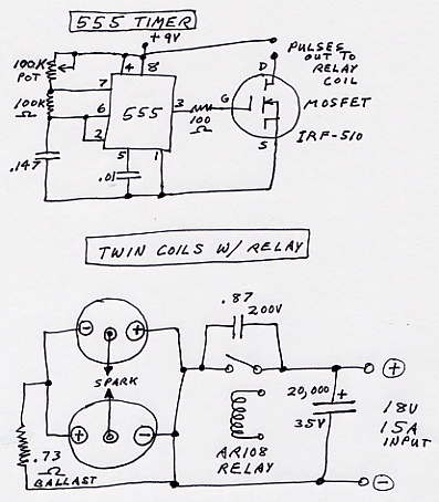
The car coils can be switched by a relay driven by a simple 555 timer circuit and a MOSFET. The relay points need a capacitor across them to reduce arcing so that the switching will be as abrupt as possible. (The points will still get rough and need polishing frequently.) Use a .7 to .9 mF, 200 V cap across the relay contacts. A ballast resistor of .8 ohms is used in series with MSD 8223 coils. We used a garage battery charger for the power with a total of 20,000 mF, 35 V caps for ripple filters. But you could use a car battery instead of a garage charger and all those capacitors.
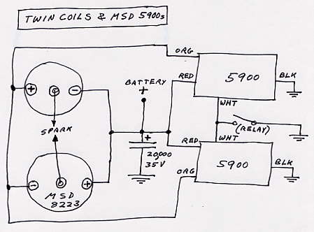
Twin aftermarket ignition systems can be employed to drive the coils. We used twin MSD 5900s in parallel. When using the 5900s, no ballast resistor is needed for the coils. This gave us 90,000 V at an undetermined current, but the loud, snapping sparks indicated that it was adequate.
A homemade X-ray tube can be made using a shortened aurora tube if a high enough vaccuum can be pulled. A tube like this and a cathode ray tube are "cold-cathode" tubes, having no glowing filament to kick out a shower of electrons, and do not produce X-rays as well as "hot-cathode" type tubes.
It should be stated that when ignition coils are not connected to spark plugs, the voltage rises unchecked to a maximum and can damage the coil. After a while one MSD Blaster 3 coil arced thru the center tower to the brass ground terminal, carbonizing the plastic and ruining the coil. So the good coil was immersed in mineral (baby) oil with just the tip 1" above the oil. This stopped any wasteful corona and carbonizing. Remove both nuts, solder wires to the top of the brass terminals and then lower the coil into a glass that is about 2 & 1/2" wide inside and about 6 & 1/2" deep. Acetone dissolves spilled oil. The MSD Blaster 3 (8223) coils were much better than other MSD coils and better than two types of Accel coils.
The spark between the coil tips is brighter at the positive tip. This tip should go to the X-ray tube anode. But the system is not pure DC, and the X-ray tube itself acts like a vacuum-tube diode and rectifies the AC.
An old RAD-1 tube used with twin auto coils in open air and 6 volts going to the filament took a 10 minute exposure to give us our first X-ray. The image shows a tungsten strip at the top, a molybdenum ore-assay boat next, then a tungsten wafer, then a lead strip and finally a wood block with a steel nail, a steel brad and a brass brad in it. There are two holes drilled in the wood block.
Other X-rays we did show that X-ray exposure time and development time are critical to imaging what it is you wish to examine inside the items X-rayed. Our fourth X-ray shows a skyrocket, tape measure, lighter and can opener. But a shorter exposure time showed the skyrocket motor's internal structure better. (See the Homemade Fireworks page.)
The neon tester connected to the cathode-ray tube (a cold-cathode tube) with one side grounded to a water pipe required 15 minutes to produce a very dim second and third X-ray. A skyrocket, a small Crescent wrench and a cigarette lighter were placed on the film cassette. But only the outline of the adjustable wrench is obvious.
The neon tester used with the old RAD-1 tube with filament current going to it and with the anode grounded to a water pipe produced a light but quite useable X-ray in 6 minutes.
Using only one 8223 coil immersed in mineral oil, the twin 5900s and with the RAD-1 filament on produced a good X-ray in 3 min. The ignition coil tip goes to the RAD-1 cathode and the anode was grounded to the battery charger negative clamp. The X-ray shows a computer mouse, a pen and a photoelectric night light. The pulse timing was 40/sec. An exposure of only 20 seconds yielded a good X-ray of the rocket motor interior.
Using one 8223 coil in oil and the NAPA AR-108 relay with .9 mF across the points produced a good X-ray after 10 minutes. That was with the RAD-1 filament on and using fresh D-cells. The .8 ohm ballast resistor must be used when not using the ignition boxes. The relay points took a beating after just one X-ray and needed to be filed and sanded smooth again.
When using one 5900, the MOSFET signal can go directly to the RPM sensor inputs, violet to the MOSFET drain and green to the +9 volt bus. Of course, with this hookup, the frequency can be set higher than 40 pulses/sec.
The best system at reasonable cost consists of a dental X-ray tube (Toshiba D-088 or D-101, for instance), one Blaster 3 coil, one 5900 ignition box and no relay on the timer/pulser board. The white wire, which is only for older cars which have contact points, is not used.
NOTES: X-ray film scratches easily when in the solutions, so use care. Touch them only around the edges when wet. (OK to touch when dry) All X-rays were taken by plugging in a long extension cord in another room to power up the battery charger and start the exposure. The 9-volt pulser battery and the 6-volt D-cell filament batteries were connected manually before leaving the exposure room.
PARTS:
- MSD Blaster 3 coil #8223
- MSD Blaster Ignition #5900
- Relay: NAPA AR-108 (if used instead of the 5900)
- MOSFET: Radio Shack 276-2072 (IRF 510)
- Caps for filtering: Radio Shack 272-1022 (4)
- See eBay for used X-ray tubes, also called "inserts". (mike@amerytel.net)
- Geiger counter: Frey 15598209 (optional)
- Neon tester: Frey 15583518 (optional)
- Induction coil: Frey 15583515 (optional) replaces timer/pulser, coil & 5900
- Kiran Hi-Plus cassette, blue-sensitive (or equivalent) 5 x 7 or 8 x 10
- Fuji RX-B film (or equivalent) 5 x 7 or 8 x 10
- Kodak Hobby-Pac, 3 trays and safelight (optional: thermometer, paper safe)
PHOTO NOTES: Mix one pint of solutions at a time. In safelight illumination, open film box and take out one sheet of film at a time from black plastic bag. (end sheets are cardboard) Seal rest of film back in box. Put film in cassette and close securely. Light can now be turned on. After each X-ray exposure, turn safelight on and light out. Remove exposed film and place in the paper safe. (Or an old film bag.) Repeat for the next X-ray. When ready to process film, pour solutions in trays. Turn light out and safelight on. Use one hand to slip film into and out of developer one at a time for the required time. Use the other hand for stop bath and fixer. Keep a paper towel handy to wipe the solutions off your hands frequently. NEVER splash stop bath or fixer hand in developer! After sliding films into solution so they are submerged, agitate the tray gently by rocking. Times are 5 min. in developer, 10 sec. in stop bath, 2 to 5 min. in fixer and 30 minutes washing in running water. Lights can be turned on when films are in fixer. Stand films on edge on paper towel angled with one side touching a back rest to dry the films.